
Kubota wiring diagrams are essential for understanding and repairing electrical systems in Kubota tractors. They provide detailed layouts of circuits, connectors, and components, aiding in troubleshooting and maintenance. These diagrams, often found in service manuals or online resources, are crucial for identifying faulty wiring, connectors, or components. By referencing models like the B7510 or L4200, users can diagnose issues such as solenoid problems or faulty connections. Clear and accurate diagrams ensure safe and effective electrical system repairs, preventing further damage and ensuring optimal tractor performance.
Overview of Kubota Tractor Electrical Systems
Kubota tractor electrical systems are designed to power essential functions like lights, sensors, and accessories. They consist of components such as batteries, alternators, wiring harnesses, fuses, relays, and control modules. These systems vary by model, with diagrams like the Kubota B7510 wiring diagram providing specific details. Modern tractors rely on complex electrical setups to support advanced features, making accurate wiring diagrams crucial for understanding and maintaining these systems. Proper maintenance ensures optimal performance and longevity. By referencing model-specific diagrams, users can identify components like the starter motor or ignition system, ensuring safe and effective repairs. This complexity underscores the importance of clear documentation for diagnosing and resolving electrical issues.
Importance of Wiring Diagrams for Troubleshooting and Maintenance
Wiring diagrams are indispensable for diagnosing and resolving electrical issues in Kubota tractors. They provide a clear visual representation of the electrical system, enabling users to trace circuits and identify faulty components. For models like the Kubota B7510, diagrams help locate issues such as solenoid problems or faulty connections. By referencing these diagrams, users can pinpoint where the electrical system may be failing, whether it’s a disconnected wire or a malfunctioning relay. This precision reduces repair time and ensures that fixes are accurate and safe. Without a wiring diagram, troubleshooting becomes time-consuming and risky, potentially leading to further damage. Regular maintenance also benefits from these diagrams, as they guide users in inspecting and replacing worn or damaged components before they cause critical failures.
Understanding the Kubota Wiring Diagram PDF
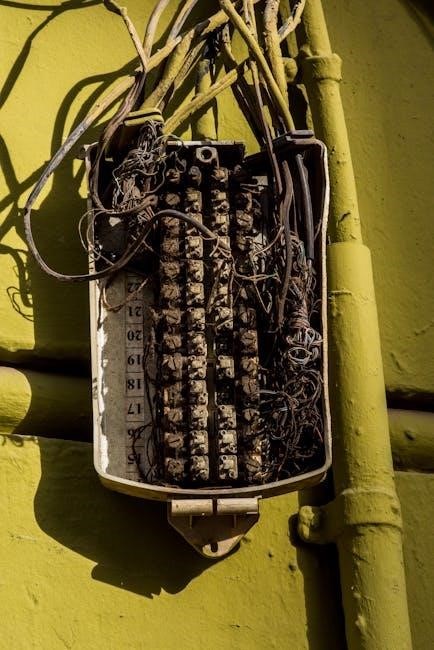
Kubota wiring diagrams provide detailed layouts of electrical systems, helping users visualize circuits, components, and connections. They are essential for diagnosing issues like faulty solenoids or wires, ensuring safe repairs.
Key Components of a Kubota Electrical Wiring Diagram
A Kubota wiring diagram includes essential components like circuit symbols, color-coded wires, connectors, and component locations. It features legends explaining symbols and abbreviations, ensuring clarity. The diagram details power sources, fuses, relays, and ground points, aiding in troubleshooting. Specific sections highlight starter circuits, ignition systems, and accessories like lights or loaders. For models like the B7510 or L4200, diagrams often include solenoid wiring and PTO connections. By referencing these elements, users can diagnose issues such as faulty solenoids or open circuits. The clear layout helps identify wiring paths, making repairs safer and more efficient. These components are vital for maintaining and repairing Kubota tractors effectively, ensuring optimal performance and longevity of electrical systems.
How to Read and Interpret the Diagram
Reading a Kubota wiring diagram begins with identifying key components like color-coded wires, connectors, and symbols. Start by locating the legend, which explains each symbol and abbreviation. Trace circuits systematically, following wires from power sources like batteries or alternators to components such as fuses, relays, and switches. Use the diagram to pinpoint ground points, ignition circuits, and accessory wiring. For troubleshooting, test continuity between connectors using a multimeter, referencing the diagram to identify potential faults. Cross-check with repair manuals or online resources for specific models like the B7510 or L4200. By understanding the layout and flow, users can diagnose issues efficiently, ensuring safe and accurate repairs. This methodical approach helps prevent errors and ensures electrical systems function optimally.
Common Electrical Issues in Kubota Tractors
Kubota tractors often face electrical issues like solenoid malfunctions, faulty wiring, and loose connections. These problems can disrupt starter circuits and accessory functionality, requiring careful diagnosis.
Identifying Faulty Wiring and Connections

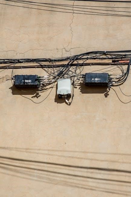
Identifying faulty wiring and connections in Kubota tractors requires a systematic approach. Start by visually inspecting wires and connectors for signs of damage, corrosion, or wear. Rodent damage is a common issue, as mice and rats often chew through wiring. Use a multimeter to test for continuity and voltage drops across suspected circuits. If a wire shows no continuity, it may be broken. Loose or corroded connections can cause intermittent electrical failures. Refer to the Kubota wiring diagram to trace circuits and pinpoint faults. Common problem areas include the solenoid, starter motor, and alternator connections. Testing these components with a multimeter can reveal issues like open circuits or shorted wires. Always disconnect the battery before performing electrical tests to ensure safety.
Diagnosing Common Electrical Problems
Diagnosing common electrical problems in Kubota tractors often begins with analyzing symptoms like faulty starting, dimming lights, or malfunctioning accessories. The Kubota wiring diagram is a vital tool, helping to isolate issues by tracing circuits and identifying components. Common problems include a faulty solenoid that clicks but doesn’t engage the starter, or a defective alternator failing to charge the battery. Testing the starter motor and checking for voltage drops can reveal wiring issues. Corrosion or loose connections in the fuse box or relay panel are frequent culprits. Using a multimeter, measure voltage at key points to pinpoint faults. For example, if the solenoid terminal shows 12V but the starter doesn’t activate, the issue may lie in the starter motor or its wiring. Always refer to the diagram to ensure accurate diagnoses and repairs, avoiding trial-and-error approaches that could worsen the problem.
Step-by-Step Guide to Using a Kubota Wiring Diagram
A step-by-step guide to using Kubota wiring diagrams helps operators identify components, trace circuits, and diagnose issues efficiently. Start by locating your model’s specific diagram, ensure safety, and gather necessary tools for repairs.
Locating the Correct Wiring Diagram for Your Model
Locating the correct wiring diagram for your Kubota model is essential for accurate repairs. Start by identifying your tractor’s model number, as diagrams vary by specific models like the B7510 or L4200. Official Kubota manuals or PDF downloads from trusted sources are the best starting points. Online forums and communities often share diagrams for popular models, such as the B7510 or Lane Shark LS3. Use the tractor’s VIN to ensure the diagram matches your exact configuration. Cross-reference with parts lists or exploded diagrams to confirm component locations. Always verify the source’s reliability to avoid incorrect or incomplete information. This step ensures you have the right tools to diagnose and fix electrical issues effectively.
Tools and Equipment Needed for Electrical Repairs
For effective electrical repairs on Kubota tractors, essential tools include a multimeter, wire testers, and circuit testers to diagnose issues like faulty connections or solenoid problems. Basic tools such as screwdrivers, pliers, and wrenches are necessary for accessing and repairing wiring components. A wiring diagram specific to your model, like the B7510 or L4200, is crucial for identifying circuits and components. Additional equipment includes insulated tools to prevent short circuits and a work light for visibility in tight spaces. Always ensure your multimeter is set to the correct voltage range, as shown in online guides, to safely measure electrical currents. Having the right tools on hand streamlines the repair process and minimizes the risk of further damage to the electrical system.
Best Practices for Safe Electrical System Maintenance
When performing electrical repairs on Kubota tractors, always disconnect the battery to prevent accidental starts or electrical shocks. Use insulated tools to avoid short circuits and ensure all components are grounded properly. Refer to the wiring diagram for your specific model, such as the B7510 or L4200, to identify circuits and components accurately. Before starting repairs, inspect wiring for damage or corrosion and replace any faulty cables. Test electrical components with a multimeter set to the correct voltage range, as shown in online guides. Avoid bypassing safety features, and ensure all repairs are done in a well-lit, dry environment. Following these practices minimizes risks and ensures reliable performance of the tractor’s electrical system. Always double-check connections and consult the official manual if unsure about any step.
Resources and References
Official Kubota manuals, online forums, and repair guides provide essential resources for wiring diagram references. Websites like Kubota’s official site and tractor repair forums offer detailed PDFs and troubleshooting tips for models such as the B7510 and L4200. Additionally, authorized dealers and third-party sellers offer comprehensive wiring diagrams and electrical system guides. These resources are invaluable for diagnosing issues like faulty solenoids or connectors and ensuring accurate repairs. Always consult trusted sources to maintain safety and reliability when working with Kubota electrical systems.
Official Kubota Manuals and Guides
Official Kubota manuals and guides are the most reliable sources for electrical wiring diagrams. These resources, available on Kubota’s official website or through authorized dealers, provide detailed schematics for specific tractor models, such as the B7510 or L4200. They include comprehensive wiring layouts, component locations, and troubleshooting guides. For instance, the workshop service manual for the B7510 includes exploded diagrams and parts listings, which are invaluable for identifying components like the K3511-55222 part. Additionally, these manuals often cover common electrical issues, such as solenoid problems or faulty connections, offering step-by-step solutions. While third-party sources may offer similar information, official Kubota materials ensure accuracy and safety. They are essential for professionals and DIYers alike, guaranteeing precise repairs and maintenance.
Online Communities and Forums for Support
Online communities and forums are invaluable resources for troubleshooting and understanding Kubota electrical wiring diagrams. Platforms like TractorByNet and Kubota Tractor Forum host discussions where users share experiences and solutions. For instance, threads about the B7510 wiring diagram and solenoid issues provide practical advice. Members often post diagrams, repair tips, and part numbers, such as the K3511-55222, to help others. These forums are especially useful for diagnosing problems like faulty connections or starter circuits. While official manuals are essential, forums offer real-world insights and community support. They foster collaboration among tractor owners and technicians, making them a key resource for maintaining and repairing Kubota equipment effectively.
Kubota wiring diagrams are indispensable for safer, more efficient tractor repairs. By understanding these diagrams and leveraging community support, users can maintain optimal performance and extend equipment life.
Final Tips for Working with Kubota Electrical Systems
Always start by disconnecting the battery to ensure safety. Use multimeters and wiring diagrams to pinpoint issues accurately. Regularly inspect connectors and wires for wear. Keep genuine Kubota parts on hand for reliable repairs. Consult online forums or official manuals when stuck. Label wires during disassembly to simplify reassembly. Test circuits gradually to avoid overloading systems. Store diagrams digitally for easy access. Consider professional help for complex faults. Maintain a clean workspace to prevent misplacing parts. Stay updated with the latest Kubota service bulletins. Prioritize safety to avoid electrical shocks or equipment damage. By following these tips, you can efficiently diagnose and repair electrical issues, ensuring optimal tractor performance and longevity.